In the previous article we modified the infrastructure to accommodate high volume of traffic. Such an infrastructure is susceptible to a single point of failure.
In this article we will further work on the infrastructure and introduce redundancy to counter the single point of failure vulnerability.
Before we proceed with the infrastructure upgrade, an important concept to clear is the use of floating IPs. Floating IPs are a kind of virtual IP address that can be dynamically routed to any network interface in the same network. Multiple hosts can own the same Floating IP address, but it can only be active on one server at any given time.
Floating IPs can be used to:
Keep the same IP address on a server, despite migration
Create a redundant firewall with stateful connection sync over our Private Network
Upgrading The Web Application Infrastructure
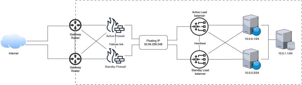
In order to overcome the single point of failure vulnerability we introduce redundancy.
Load Balancers: While making the load balancers redundant, only one can stay in active state and serve incoming traffic. The load balancers share a direct link between them, used for heartbeat signal, which allows the other load balancer to change its state to active upon the failure of the currently active load balancer. Both load balancers can respond to similar traffic as they share a floating IP when active.
Firewalls: Similar to load balancers, firewalls can also have a single active firewall. Using the failover link between the firewalls, they share their status and the standby firewall takes over when the currently active firewall goes down.
Gateways: Both gateways can operate in active states, forwarding traffic to the active firewall and destination load balancer.
Step 3: Transport Control Protocol (TCP)
The SYNC message from client reaches the gateway. The gateway forwards the packet to the active firewall, after evaluation the packet is forwarded to the active load balancer, it decides which node this new packet should go to based on the algorithm discussed in previous article. The load balancer decides that the message should go to the first node (10.0.0.1/24). The server responds and subsequent packets follow the same route i.e. communicates with the first node.
In the previous article we have discussed a very basic architecture to host a web application and how the web request cycle is carried out. In this article we will modify the architecture to set a starting point for hosting an application when a high volume of traffic is expected.
A single server has limited resources and when bombarded with millions of requests, it is bound to choke. In order to handle such a high volume traffic, resources must be added to the existing setup. This process is called scaling.
When it comes to hardware, there are two types of scaling.
Vertical Scaling: When resources are added to the existing hardware e.g. RAM, CPU or hard disk.
Horizontal Scaling: When nodes are added to the existing pool of nodes.
In this article we will focus on horizontal scaling and add nodes and relevant components to make the architecture work.
Upgrading The Web Application Infrastructure
We started with an infrastructure as shown:
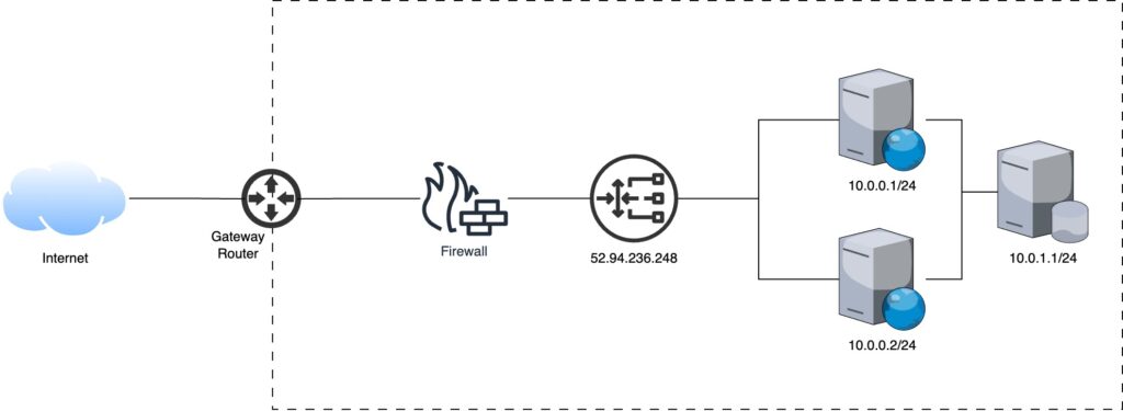
Our goal is to scale the environment horizontally by adding nodes for the application to run and a mechanism to control the traffic to each node. We call that load balancing and can be achieved with a load balancer either a hardware or software.
Load balanced application infrastructure
Load balancer acts as a traffic proxy and distributes network or application traffic across endpoints on a number of servers running the same code base of the application. The load balancer distributes traffic based on algorithms such as:
Round robin
Threshold
Random with two choices
Least connections
Least time
URL hash
Source IP hash
Consistent hashing
Web Request Cycle
With the upgrade in the infrastructure the web request cycle changes slightly. The load balancer receives all the web requests and distributes them amongst the pool of resources. Step 3 of the previous article introduces this change.
Step 3: Transport Control Protocol (TCP)
The SYNC message from client reaches the load balancer, it decides which node this new packet should go to based on the algorithm discussed. The load balancer decides that the message should go to the first node (10.0.0.1/24). The server responds and subsequent packets follow the same route i.e. communicates with the first node.
What happens when we visit a website in a web browser? To the user a web page opens up in a few seconds depending on the size of web page content, but behind the scenes different components of the web or internet work together to load that particular web page in the browser.
In this series we will explore how a web request is navigated across the internet and fulfilled by the web application hosted in different infrastructures. For simplicity we will consider a monolithic application architecture.
In simple terms the application architecture refers to the framework and principles in which the application components collaborate to perform the intended function.
Types of application architectures:
Monolithic
Client-Server
Microservices
Server less
Progress Web App
Application infrastructure is the underlying hardware and software components that enables the system to function. This include load balancers, firewalls, servers, and VMs etc.
Web Application Monolithic Architecture
Monolithic application architecture defines a web application as a single unit, i.e. the user interface, business logic and data access are tightly coupled in a single code base. e.g. WordPress
Web Application Infrastructure
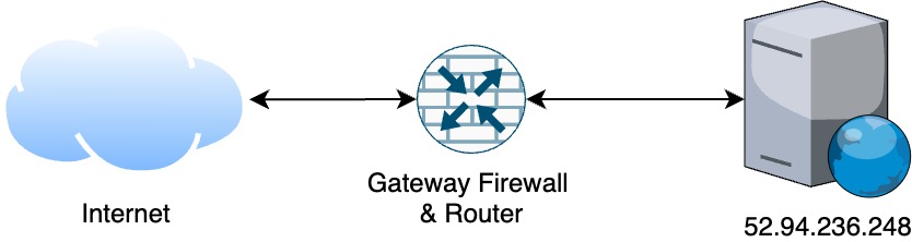
In order for a web application to serve its users, it must be deployed on a server accessible via the internet. The very basic setup required for such applications include:
Server or a VM with web server (Apache or Nginx) installed
Public IP (IPv4 for simplicity)
Router & Firewall
The infrastructure diagram is depicted below:
Bare Minimum Web Application Infrastructure
Web Request Cycle
When a user types in a URL (Uniform Resource Locator) in their web browsers the web browser loads that particular resource after a series of communication with the components on the internet. The whole process is carried out in steps:
The URL consists of a protocol (https://) and a domain name (amazon.com) also called a fully qualified domain name (FQDN). Often, URLs will have www in them which is a sub-domain and references the deprecated phrase “World Wide Web” popular in 1990s.
Step 2: Name Resolution Through Domain Name Server (DNS)
Machines are identified by their IPs in a network. IP (Internet Protocol) is an address either v4 (32-bit numeric) or v6 (128 bit hexadecimal) that provide identification to any network device capable of communication on Layer-3 of the OSI or TCP/IP stack. Thus, to access a web application, we require the IP address of the server it is hosted on. In the case of https://amazon.com the IP address can be acquired by using a tool called ping, which is 52.94.236.248 as shown:
Ping results for amazon.com
Accessing a web application or website through IP makes memorization difficult. To overcome this problem domain names are used to identify Internet resources, with a text-based label that is easier to memorize than the numerical or hexadecimal addresses used in the Internet protocols.
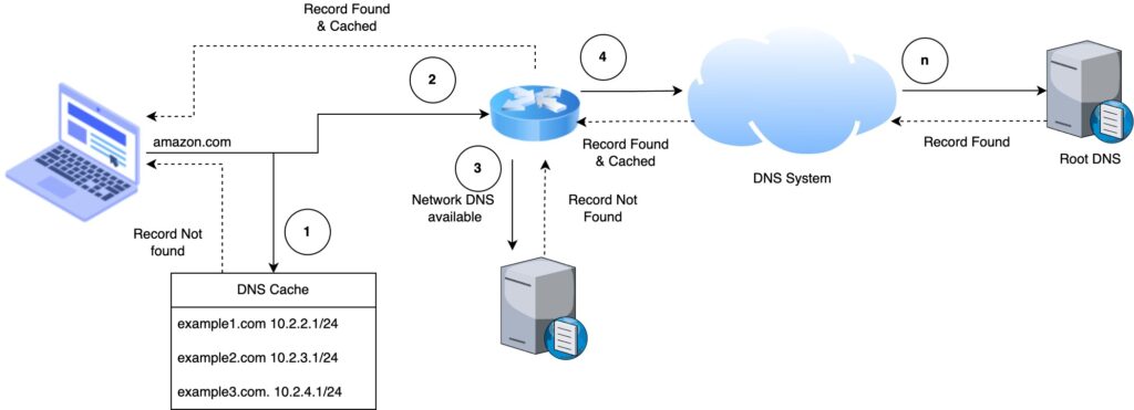
Domain Name Server (DNS) is used to map the text-based label to the IP. The root / authoritative DNS contains all the registered domain names. The first-level set of domain names are the top-level domains (TLDs), including the generic top-level domains (gTLDs), such as the prominent domains com, info, net, edu, and org, and the country code top-level domains (ccTLDs).
DNS entries are cached at different levels in the network such as ISPs, organization DNS, routers and OS for faster resolution. At first, the DNS cache maintained by the browser is checked, if an entry does not exist, next the gateway router or closest DNS, if fails, next the ISP DNS so on and so forth until the root DNS.
DNS System
In order to make the resolution direct we can enter public DNS available in OS network configuration. Public DNS provided by Google are 8.8.8.8 and 8.8.4.4
Once the domain name is resolved the browser receives an IP for the resource.
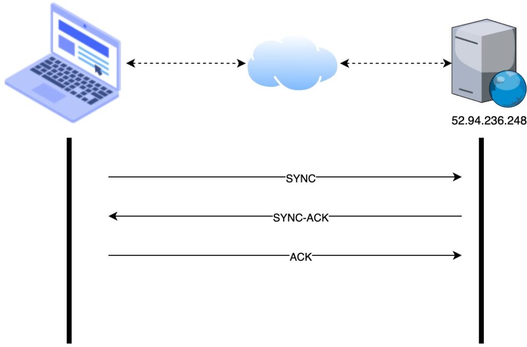
Step 3: Transport Control Protocol (TCP)
The OS initiate a TCP connection with the server. The connection is established using a three-way handshake.
TCP Three-way Handshake
The SYNC message is sent from the user device to the server
The server responds with an acknowledgement (SYNC-ACK) message that the message has been received
The user device responds with an acknowledgement (ACK) message informing the server that it had received the acknowledgement sent by it.
At this stage the connection has been established and data can transmit between the two parties.
Step 4: Hypertext Transfer Protocol (HTTP)
Web application data is communicated using the application layer protocol referred to as HTTP. The browser sends a GET request to the server requesting the resource from the web server. In that request the browser adds its identifier in the packet header called user-agent. The value can be used to present a specialized web page for that device. e.g. a web browser on mobile phone can have a different layout than a desktop one.
Step 5: Web server response
The web server (Apache or Nginx) accepts the request, a back-end programming language or framework (PHP, Ruby, Python) decides what content to send, generates or loads that content and sends the response in HTML (Hypertext Markup Language) as shown:
<!DOCTYPE html>
<html>
    <head>
        <!-- head definitions go here -->
    </head>
    <body>
        <!-- the content goes here -->
    </body>
</html>
Step 6: Browser renders the content
The response content is only text and the browser responsibility is to render the text into a proper format. The browser reads the response line by line and start loading other resources i.e. static files such as media, scripts and styles.
Upon downloading static files the browser applies styling and runs the JavaScript linked to the page and the result looks as shown