In the previous article we modified the infrastructure to accommodate high volume of traffic. Such an infrastructure is susceptible to a single point of failure.
In this article we will further work on the infrastructure and introduce redundancy to counter the single point of failure vulnerability.
Series Articles
Floating IPs
Before we proceed with the infrastructure upgrade, an important concept to clear is the use of floating IPs. Floating IPs are a kind of virtual IP address that can be dynamically routed to any network interface in the same network. Multiple hosts can own the same Floating IP address, but it can only be active on one server at any given time.
Floating IPs can be used to:
- Keep the same IP address on a server, despite migration
- Implement failover in a high-availability cluster
- Implement zero-downtime Continuous Deployment (CD).
- Create a redundant firewall with stateful connection sync over our Private Network
Upgrading The Web Application Infrastructure
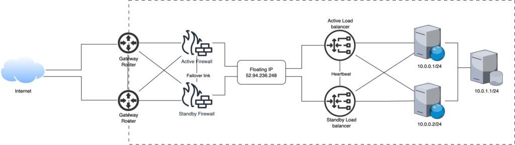
In order to overcome the single point of failure vulnerability we introduce redundancy.
- Load Balancers: While making the load balancers redundant, only one can stay in active state and serve incoming traffic. The load balancers share a direct link between them, used for heartbeat signal, which allows the other load balancer to change its state to active upon the failure of the currently active load balancer. Both load balancers can respond to similar traffic as they share a floating IP when active.
- Firewalls: Similar to load balancers, firewalls can also have a single active firewall. Using the failover link between the firewalls, they share their status and the standby firewall takes over when the currently active firewall goes down.
- Gateways: Both gateways can operate in active states, forwarding traffic to the active firewall and destination load balancer.
Step 3: Transport Control Protocol (TCP)
The SYNC message from client reaches the gateway. The gateway forwards the packet to the active firewall, after evaluation the packet is forwarded to the active load balancer, it decides which node this new packet should go to based on the algorithm discussed in previous article. The load balancer decides that the message should go to the first node (10.0.0.1/24). The server responds and subsequent packets follow the same route i.e. communicates with the first node.
Leave a Reply